How to build a lipo battery pack?
2025-10-21
The Power Heart of Drones: Unveiling the Artistry Behind Lithium Polymer Battery Packs
Assembling a drone battery pack is a skill brimming with challenges and rewards. It not only allows you to fully customize endurance and power but also provides deep insight into the drone's energy core. However, this is far from a simple soldering game—it's a precise art that balances electronic knowledge, manual dexterity, and safety awareness. This article will systematically guide you into the world of drone LiPo battery pack construction.

I. Core Principles: Why Series and Parallel Connections?
Before diving in, grasp the fundamental electrical architecture of battery packs. We achieve different objectives through two methods:
Series Connection: Increases Voltage
Method: Connect the positive terminal of one cell to the negative terminal of the next cell.
Effect: Voltage increases while capacity remains unchanged.
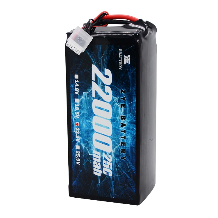
Drone Application: Higher voltage in the power system reduces current draw at equivalent power output, improving efficiency and delivering quicker power response. Common 3S batteries provide approximately 11.1V, while 6S batteries deliver around 22.2V.
Parallel Connection: Increasing Capacity
Method: Connect the positive terminals of all cells together, and the negative terminals together.
Effect: Capacity increases while voltage remains unchanged.
Drone Application: Directly extends flight duration. For example, paralleling two 2000mAh cells yields a total capacity of 4000mAh while maintaining the voltage of a single cell.
Most drone batteries employ a “series-parallel” structure.
Example: “6S2P” consists of 6 cell groups connected in series for high voltage, with each group comprising 2 cells connected in parallel for increased capacity.
II. Four Core Elements of Battery Packs
Cells: Quality is fundamental. Always select power cells from reputable brands with consistent specifications.
Consistency is the lifeline of pack assembly, encompassing capacity, internal resistance, and self-discharge rate. New cells from the same production batch are preferred.
Nickel Ties: The “conductive bridges” between cells. Select appropriate material, width, and thickness based on the battery's maximum continuous current. Insufficient cross-sectional area causes overheating and poses safety risks.
Battery Management System (BMS): The “intelligent brain” of the battery pack.
Housing and Wiring:
Wires: Main discharge cables (e.g., XT60, XT90 connectors) must be sufficiently robust (e.g., 12AWG silicone wire) to handle high currents.
Balancing Head: Used to connect to the BMS or balancing charger; must correspond to the number of cells (S).
Housing: Heat-shrink tubing or rigid casing provides insulation, moisture protection, and physical shielding.
III. Practical Steps: Building a Complete System from Scratch
Preparation:
Essential Tools: Spot welder, multimeter, heat-resistant gloves, safety goggles.
Work Environment: Well-ventilated area free of flammable materials; work surface covered with an anti-static mat.
Step 1: Sorting and Testing
Test and sort all cells using a capacity tester and internal resistance meter. Ensure parameters of cells in each parallel or series group are as consistent as possible. This forms the foundation for effective BMS balancing later.
Step 2: Planning and Layout
Plan the physical cell layout based on your target configuration. Isolate cells with insulating spacers to prevent short circuits.
Step 3: Spot Welding Connections
Parallel Group Welding: First, weld the cells to be connected in parallel using nickel strips. Ensure the connection is secure and has low resistance.
Series Connection: Treat the parallel groups as a single unit. Then, connect them in series using nickel strips, linking positive and negative terminals to form complete “cell strings.”
Welding Main Sampling Lines: Weld the BMS voltage sampling ribbon cables to the positive and negative terminals of each cell string.
Step 4: BMS Installation and Final Welding
Secure the BMS in the designated position.
First, insert the sampling ribbon cable into the BMS. Use a multimeter to verify the correct voltage for each cell string.
After confirmation, weld the positive (P+) and negative (P-) terminals of the main discharge cable to the corresponding ports on the BMS.
Step 5: Insulation and Encapsulation
Wrap the cell assembly with insulating materials like kraft paper or epoxy board to prevent internal short circuits.
Slide heat shrink tubing over the assembly and evenly heat it with a heat gun to form a tight seal around the battery pack.
Install the balancing connector and main discharge connector.
Step 6: Initial Activation and Testing
Connect the assembled battery pack to a balancing charger and perform the first charge at a low current (e.g., 0.5C).
Continuously monitor the voltage of each cell to verify proper BMS balancing function.
After charging completes, let the pack rest for several hours. Re-check voltages to confirm no abnormal voltage drops.
IV. Safety Guidelines
Always wear safety goggles: Protect your eyes from arcs or explosions caused by accidental short circuits during any operation.
Prevent physical punctures: Handle cells with extreme care, as if they were eggs.
Use Explosion-Proof Bags: Initial testing and charging must be conducted inside explosion-proof bags.
Insulate Tools: Ensure all metal tool handles are insulated to prevent simultaneous contact with positive and negative terminals.
V. Future Trends: Upgrade Directions for LiPo Battery Packs
Currently, drone LiPo battery packs are evolving toward “high energy density + intelligent functionality”: Semi-solid LiPo cells have achieved energy densities of 400Wh/kg (a 50% increase over traditional cells), enabling future “doubled endurance at the same weight.” Intelligent BMS systems will incorporate temperature alerts and cell health monitoring, providing real-time battery status feedback via apps to further mitigate safety risks.


